System architecture design for industrial-vehicle vision terminals
Vehicle vision results need to drive alerts, records and peripheral responses. Planning covers architecture, interfaces and interaction for two terminals; design references are available, while whole-product effects and performance require prototype validation.
Project stageProduct planning and architecture design; effects and performance require prototype validation
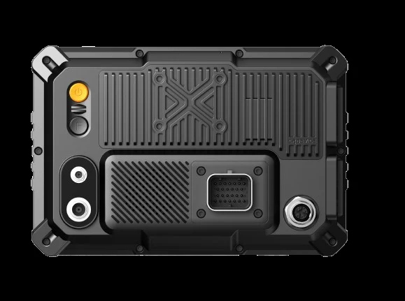
Solution-design illustration · not a product photograph
Project overview
Product / platform
SF-425 Pro and the SF-131 touch version
Proposed responsibilities
Two architecture routes across the main processor, vision-recognition module and MCU
Engineering focus
Recognition-result interfaces, device responses, touch workflows and whole-product constraints
What the product needed to solve
The terminal handles vehicle-surround and driver images, combines results with vehicle state, and drives alerts, records and peripherals. Responsibilities must be divided across the main processor, recognition module and MCU.
Engineering approach
How the engineering work fits together
01
Choose architecture routes for different complexity
SF-425 Pro planning assigns vision, workflows, display, recording and networking to the main processor, with an MCU for interface expansion. The SF-131 touch route separates recognition modules from the screen-control MCU; some capabilities remain future planning.
02
Connect recognition results to device workflows
Organize image input, recognition results, zone rules, alerts and event retention. Functions are planned by applicable product, with explicit interfaces and later validation for algorithm cooperation, lens adaptation and product integration.
03
Plan interaction and whole-product constraints together
Organize viewing, parameters, calibration, records and settings into workflows, while planning power, CAN, serial interfaces, connectors, enclosures and mounting. Environmental suitability, interference protection, ingress protection and production tests remain validation inputs.
Engineering evidence
See the material, its purpose and the limits of what it demonstrates
Planned interface-design reference
BSD channel and zone-configuration interface reference from project planning material.
The planned interface does not establish simultaneous validation of cameras, recognition, display and recording, or real-world safety effectiveness.
Architecture planning for two product routes
Two product architectures redrawn from project material; both represent planning and design.
The project remains at product-planning and architecture-design stage; the diagram does not establish production release, certification, whole-product performance or delivery.
What the project has produced
Product and architecture planning
Hardware/software responsibilities and whole-product references for two product routes, rather than delivered prototypes.
Interfaces and workflow relationships
Planned interfaces from vision results to zone rules, alerts, event retention and peripheral control.
Interaction and validation inputs
Touch, parameter and calibration interface references, with whole-product constraints for later prototype validation.
Engineering foundation
Current product planning defines two architecture routes, the relationship from vision results to device responses, and references for interaction, interfaces and whole-product design.
Validation scope and limits
This case presents product planning and architecture design. Planned configurations do not establish that multi-channel capture, display, inference and recording have been validated together.
This case presents project materials and stage outcomes. Deliverables, test conditions and acceptance scope are confirmed for the agreed project version.